퀘스트 4/7 - A7/ M4 예제 응용 데모 시현
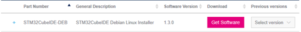
@ STM32CubeIDE Download
% https://www.st.com/en/development-tools/stm32cubeide.html
% Ubuntu OS 환경에서는 STM32CubeIDE-DEB를 받아 설치.
% Ubuntu 18.04.4 OS 환경에서 STM32CubeIDE-Lnx를 받아 설치 시 설치 후 실행까지 확인하였으나, 재부팅 시 부팅 멈춤.
% 총 3회 시도하였으나 동일. STM32CubeIDE-DEB 설치 시 문제없이 동작.
@ STM32CubeIDE 압축해제 및 설치
$ unzip en.st-stm32cubeide_1.3.0_5720_20200220_1053_amd64.deb_bundle.sh.zip
$ sudo sh st-stm32cubeide_1.3.0_5720_20200220_1053_amd64.deb_bundle.sh
% default folder에 설치 : /opt/st/stm32cubeide_1.3.0/
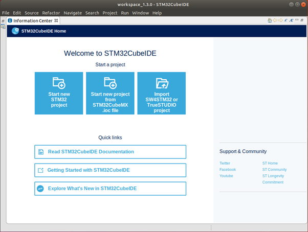
@ STM32Cube 실행
$ /opt/st/stm32cubeide_1.3.0/stm32cubeide
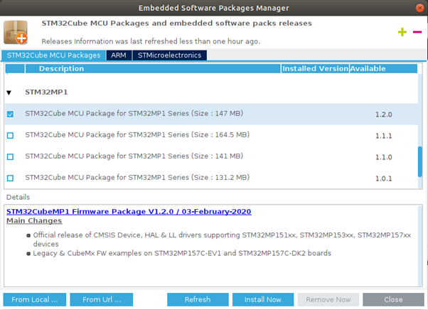
@ STM32MP1 Software Package 업데이트
% Menu -> Help -> Manage embedded software packages
% STM32Cube MCU Package for STM32MP1 Series, v1.2.0 선택 후 'Install Now' Click.
DK2 보드 정보 확인
@ 회로도 확인 ( mb1272-dk2-c01_schematic.pdf, Page13 )
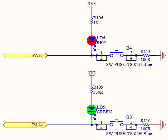
% RED LED를 동작하기 위해 PA13 = OUTPUT, PA13 = Low 에서 LED On.
% USER1 S/W를 사용하기 위해 PA14 = INPUT, Pull-up 이 되어 있지 않음.
CubeIDE(+CubeMX)로 EXTI 및 GPIO output을 제어하는 펌웨어를 작성하고 디버깅
@ Project 생성
% Menu -> File -> New -> STM32 Project
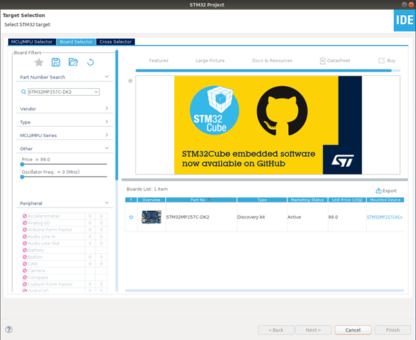
% Board Selector -> STM32MP157C-DK2 검색 및 보드 선택.
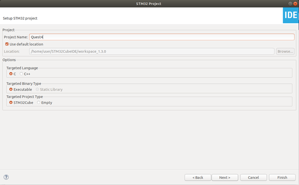
% Project Name 입력 후 'Finish' Click.
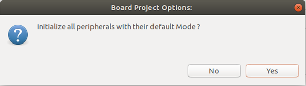
% Default Mode -> 'Yes' Click.
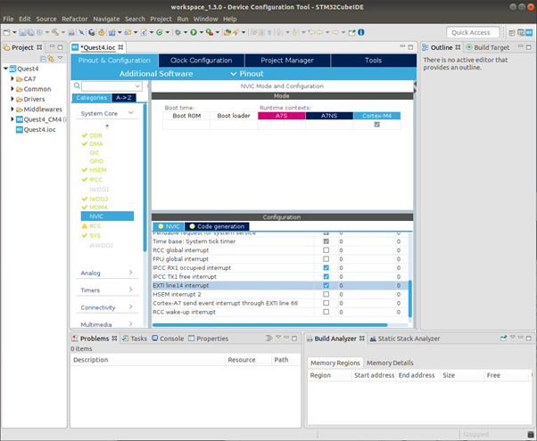
@ Pin 설정 및 Code 생성
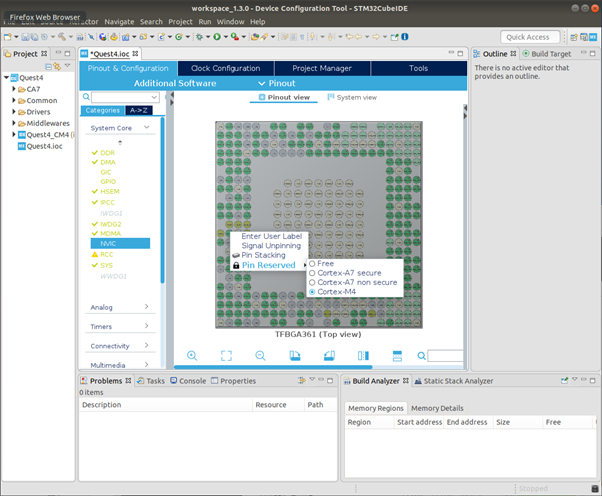
% PA13 pin을 M4에서 사용하도록 설정.
% PA13 우클릭. Pin Reserved -> Cortex-M4 선택.
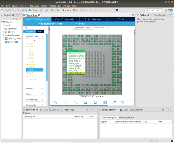
% PA14를 External Interrupt Input으로 설정.
% PA14 클릭. GPIO_EXTI14 선택.
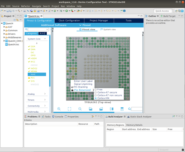
% PA14 pin을 M4에서 사용하도록 설정.
% PA14 우클릭. Pin Reserved -> Cortex-M4 선택.
% Systme Core -> GPIO -> PA14의 GPIO Mode를 'External Interrupt Mode with Falling edge Trigger Detection' 선택.
% Pin Mode를 먼저 선택 후 프로세서 할당 해야 됨. Pin Mode 변경시 프로세서 할당 해제됨.
% Interrupt Mode가 활성화 되지 않는다면 Pin Mode 다시 확인.
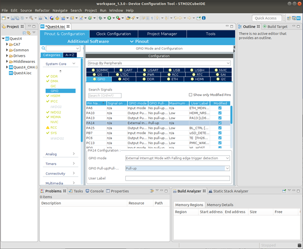
% External Interrupt 활성화.
% Interrupt가 활성화 되지 않는다면 Pin Reserved 다시 확인.
% Menu -> Project -> Generate Code 선택하여 Code 생성.
@ Code 구현 및 Build
% HAL_GPIO_EXTI_Falling_Callback() 함수 내에 구현.
% 14번 Pin에 의해 Interrupt 발생시 PA13 Toggle.
% Menu -> Project -> Build All 선택하여 Build 수행.
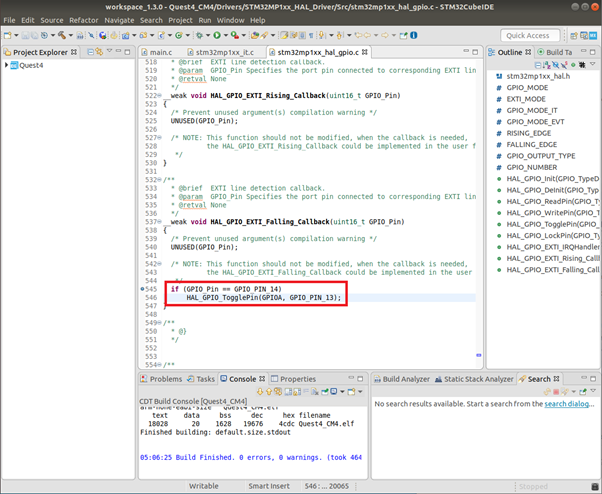
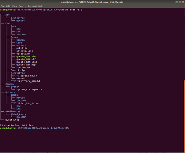
% Project tree 및 Output File 확인.
1. STM32CubeMX와 STM32CubeIDE를 사용하여 작성하고 빌드된 M4 프로젝트의 디렉토리 구조를 출력하여 제출.
@ Debugger 설정 및 Debugging
% ST-Link를 연결하고 DK2 Board의 전원을 입력함.
% 이때 eth0 or usb0 중 하나만 연결함. 두개 모두 연결 시 Board와 연결되지 않는 문제가 있었음.
% DK2 Board의 eth0 or usb0의 IP address 확인함.
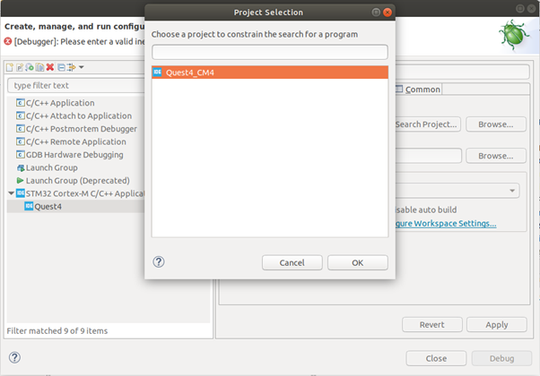
% Menu -> Run -> Debug Configurations 선택.
% STM32 Cortex-M C/C++ Application -> Quest4 선택. Main -> Project의 'Browse...' Click.
% Quest4_CM4 선택 후 'OK Click'. *.elf file이 자동으로 추가됨.
% Debug Tab의 Load Mode -> Inet Address의 '불러오기' Click. 자동으로 IP Address 가 Loading 됨.
% Debug probe는 'ST-Link(OpenOCD)' 선택.
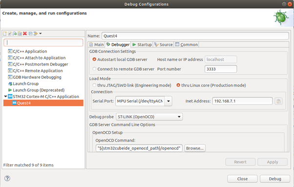
% 하단의 'Debug' Click 하면 현재 연결을 끊고 elf file을 DK2 Board에 Loading후 Debugging을 시작함.
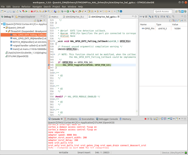
% DK2 Board의 USER1 Button을 눌러 Interrupt 발생 후 Break Point에 잡힌 상태.
2. STM32CubeIDE상에서 USER1 버튼을 누를 때 Interrupt handler 또는 HAL callback에서 브레이크 포인트를 설정하여 캐치된 상태의 화면을 캡쳐하여 제출
어플리케이션을 target에 배포(설치)
@ Output file(*.elf)을 DK2 Board로 복사
$ cd ~/STM32CubeIDE/workspace_1.3.0/Quest4/CM4/Debug
$ scp Quest4_CM4.elf root@192.168.7.1:/lib/firmware
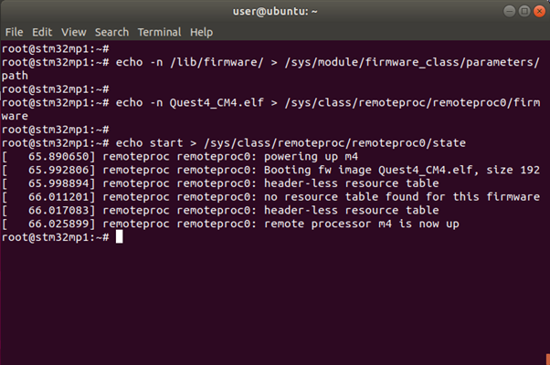
@ Linux kernel의 console에서 firmware for M4를 Loading 및 실행을 Manual로 확인.
$ echo -n /lib/firmware/ > /sys/module/firmware_class/parameters/path
$ echo -n Quest4_CM4.elf > /sys/class/remoteproc/remoteproc0/firmware
$ echo start > /sys/class/remoteproc/remoteproc0/state
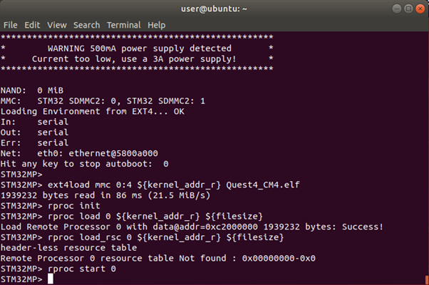
@ U-Boot의 console에서 firmware for M4를 Loading 및 실행을 Manual로 확인.
% bootfs로 firmware for M4 복사
$ mount /dev/mmcblk0p4 /boot
$ cp rproc-m4-fw.elf /boot/
$ sync
% 재부팅 후 U-boot 진입
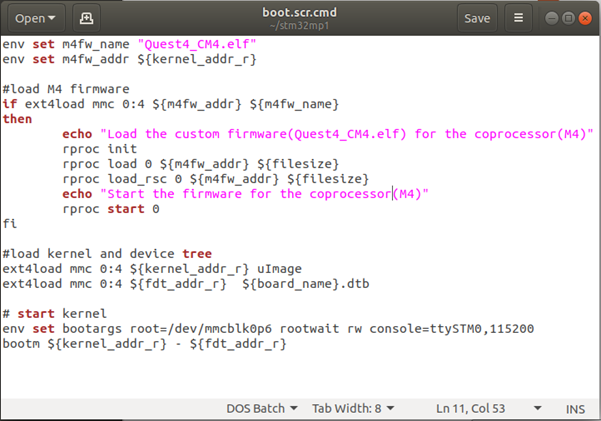
$ ext4load mmc 0:4 ${kernel_addr_r} Quest4_CM4.elf
$ rproc init
$ rproc load 0 ${kernel_addr_r} ${filesize}
$ rproc load_rsc 0 ${kernel_addr_r} ${filesize}
$ rproc start 0
@ booting시 firmware for M4가 자동 Loading 및 실행방법.
% 참고 : https://wiki.st.com/stm32mpu/wiki/Linux_remoteproc_framework_overview
* to use an initramfs
* compile remoteproc as a module and not as kernel built-in driver
% 참고 : https://wiki.st.com/stm32mpu/wiki/How_to_start_the_coprocessor_from_the_bootloader
* the bootcmd (needing U-Boot recompilation)
* a generic DISTRO boot script
* the FIT image
% 총 다섯 가지 방법 중 ‘a generic DISTRO boot script’ 선택 하였음.
@ boot.src.uimg에 firmware for M4를 Loading 및 실행 명령어 추가.
% 참고 : https://wiki.st.com/stm32mpu/wiki/How_to_start_the_coprocessor_from_the_bootloader#Start_from_a_generic_DISTRO_boot_script
% boot.src.uimg를 위한 Script (boot.src.cmd) 생성.
% U-boot에서 Manual로 firmware for M4를 Loading 및 실행 방법과 동일하게 작성.
% Loading과 실행 시 쉽게 확인 가능하도록 Message 추가.
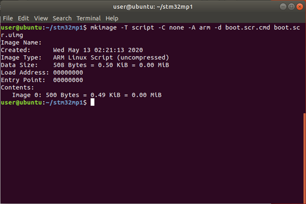
@ boot.src.uimg 생성 및 복사.
$ mkimage -T script -C none -A arm -d boot.scr.cmd boot.scr.uimg
$ scp boot.scr.uimg root@192.168.7.1:/home/root
% DK2 Board에서 boot.src.uimg 복사
$ cd /home/root/
$ cp boot.scr.uimg /boot/
$ sync
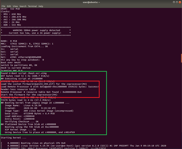
@ Rebooting 후 booting message에서 firmware for M4가 Loading 및 실행 Message 확인
3. M4 펌웨어를 linux 부팅시에 로딩되도록 포함한 뒤에 부팅 로그를 캡쳐하여 제출.
@ 시연 영상
4. DK2 target 보드를 부팅(리셋)하여 바로 USER1 버튼을 누를 때마다 LD6가 토글되는 것(M4 펌웨어가 동작하는 것)을 영상으로 캡쳐하여 제출.
Linux Kernel이 Load 되기전에 bootloader에서 firmware for M4 가 먼저 Load 되기 때문에 Linux Kernel Loading 중에도 동작됨.
.